Smart Lock
ECE 5725 Final Project - Spring 2022
Alisha Kochar (ak2255), Anusha Nambiar (aan29)
Demonstration Video
Introduction
Our Smart Lock uses two-factor authentication to grant access to users recognized by the system. Upon access being granted, all users can lock or unlock the system. The first method of authentication uses one of the piTFT buttons, which upon being pressed, verifies that there is a user associated with that button. If recognized by the system, the system will then use the piCamera to scan the user’s face and use facial recognition to either grant access if the user is the correct individual associated with the piTFT button or deny access if the user is not the correct individual associated with the piTFT button –– our second measure of authentication. Our smart lock has two modes: superuser or regular user. An individual with superuser rights has the ability to add new users, remove existing users, and view the recent access history associated with their tag, as well as the ability to lock and unlock the lock. A regular user only has the ability to either lock or unlock the lock, and view the recent access history associated with their tag. The Smart Lock has been developed using a Raspberry Pi 4B as the final project of the ECE 5725 Design with Embedded OS class at Cornell University.
Project Objective
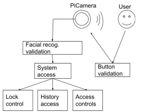
- Permit users access to the system via an authentication process (1. recognizable piTFT button, 2. facial recognition via ML)
- Permit actions for users and recent history per each user mode (superuser vs. regular)
- Send text alerts to superusers after denied access attempts
- Control bolt lock using an actuator
Design and Testing
The following is the timeline we followed for our project:
- Week 1: initial scheduling/planning, set up basic RFID reading,
set up camera
- Week 2: code to write to history to RFID tags, linear actuator (lock hardware) setup,
lock control logic
- Week 3: facial recognition module, button logic
(switched from RFIDs to piTFT buttons)
- Week 4: piTFT display, code to add/remove users, store user hist from button press
and display to piTFT
- Week 5: project write-up (website) and final demo
Week 1
Our initial design project integrated an RFID as the first measure in user-authentication.
We worked on setting up the RFID-readTag module which would read a tag scanned by a user, and
could take one of two actions:
1) allow the user to move to the second measure of user-authentication
(i.e. the facial recognition module) if the tag is recognized by the system or
2) depict
an error message to the screen indicating that the tag is not recognized by the
system
Initially, we had some issues with integrating the RFID with the RPi –– this was caused by the piTFT and RFID
reader
sharing the
same SPI. Thus, we needed to edit our /boot/config.txt file to register another SPI for our RPi. Once we
editied this file, we were able to pair our RFID receiver to the RPi and use the
pirc522
Python library
to develop our RFID module. We used the following hardware setup to connect the RFID receiver to the RPi:
| RFID | Pi Pin | Pin Name |
|---|---|---|
| SDA | 37 | GPIO26 |
| SCK | 40 | SPI1 SCLK |
| MOSI | 38 | SPI1 MOSI |
| MISO | 35 | SPI1 MISO |
| IRQ | 29 | GPIO5 |
| GND | 39 | Ground |
| RST | 31 | GPIO6 |
| 3.3V | 17 | VDD_3V3 |
Once our hardware and software setups were complete, we were able to successfully read the Unique IDentifiers
(UID)
for each tag waved near the RFID receiver.
We then moved onto integrating the piCamera with our RPi. We used the Raspberry Pi Camera V2 and connected it
to the
RPi via the ribbon connector on the camera into the connector slot on the RPi. Please refer to the following
image for our setup:

Week 2
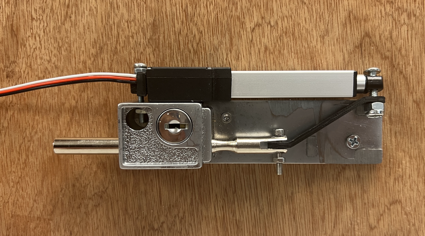
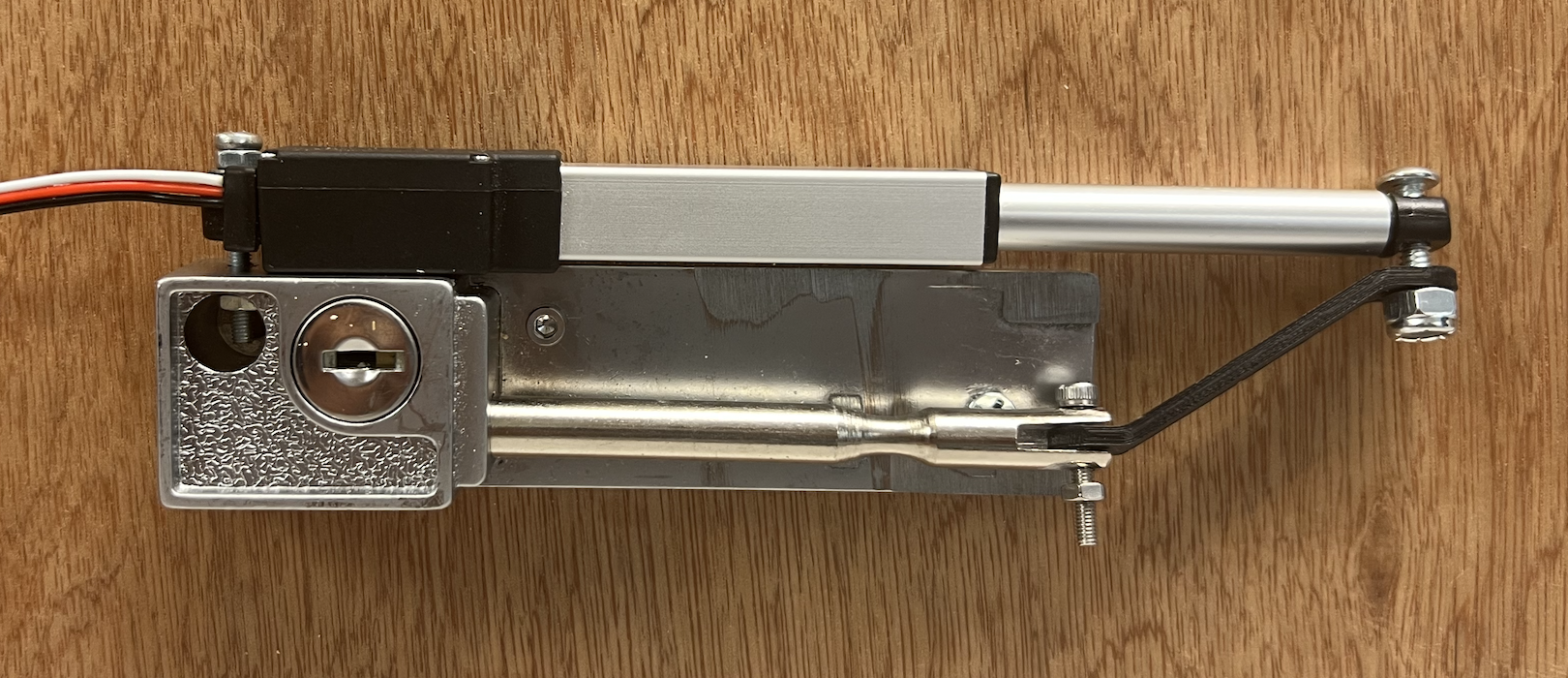
Connecting the linear actuator to our RPi was fairly simple and somewhat familiar due to working with the DC
motors
we used in Lab 3. The linear actuator we used required a +6V drive, so we connected it to the bench power
supply. We also used the bench power supply to create a common ground between the RPi and the
actuator.
We then connected the white RC input signal wire from the linear actuator directly to the RPi and breadboard
via pin number 36 (GPIO16).
We then developed a simple Python program (actuator.py) to test the values needed to retract and expand the
linear actuator ––
correlating to locking and unlocking the physical lock.
Once this was complete, we completed the hardware setup for the lock, which can be seen in the following
image:
During this week we also wrote code to write user access histories to the RFID tags. Tyipcal RFID tags have sixteen sectors, and these sectors are divided into four blocks of sixteen bytes each. The first block in the first sector (S0B0) cannot be written to because it contains manufacturer data, but we were able to use the remaining blocks to store access histories. We stored the date (year, month, day), time (hour, minute, second), and whether or not access was granted (True/False) for the three most recent access attempts. Data was stored in order of newest to oldest, so at every new access attempt, the new entry was stored at the top, the oldest entry was removed, and the others were shifted down. Our original function to display the history would read the data stored on the RFID tag and display it on the piTFT screen.
Week 3
The first step in developing the facial recognition code was setting up and getting comfortable with the
PiCamera. Once we were able to take both single photos of ourselves and a series of photos from a stream, we
began working with facial detection.
The facial detection code used a Haar cascade classifier (from the Python module openCV) to detect faces in an
image and then draw a rectangle around them. We did not end up using this code in the final project because we
wanted to focus our display on the piTFT screen, but it helped us better understand the piCamera and openCV
modules.
We first tried to build our facial recognition feature with the module DeepFace. This module is very powerful, and gives
accurate predictions with only one training image. When we tested the code we wrote with this module on our
laptops, it worked correctly, but when we tried to run this code on the RaspberryPi, it did not work. We
discovered that this is because DeepFace uses TensorFlow, another commonly used Machine Learning module for
Python. When we tried to install TensorFlow to resolve the dependency, we found that there is no stable
version
of TensorFlow compatible with Python 3.9 (the version we are using on our RaspberryPi). We attempted to
downgrade to Python 3.8, but that caused other compatibility issues, so we decided not to use the DeepFace
module.
After finding that DeepFace was not feasible, we switched to the module Face Recognition. Our initial training code with
this
module
read in all the
users photos, stored on the device in folders titled "userN" (where N is the user number), detected and
encoded
the faces in each photo, and then stored these encodings and their associated user names in lists. The
recognition code then compared the face encoding in a test image against all the other face endocings, and
returned the name associated with the encoding most similar to the test image.
Initially, we had no way of storing these encodings, so we had to run the training every time before we could
run an image comparision. This made our code incredibly slow, and not feasible for an embedded system. We
thought about storing the data in a text file, but that made it
difficult and unwieldy to access since the encodings are formatted as large matrices. We eventually decided to
use the
Python
library Pickle. We used Pickle to serialize the
data
(convert it
into byte streams) and then store this in a file on the RPi. We could then de-serialize the data quickly back
into
the original format. This allowed us to access the encodings without having to run through all the images and
calculate them evey time. We also modified our get_encodings function so that we did not have to re-add
existing
users every time we wanted to train the data, but rather just add new users' information to the end of the
file.
Because our encodings and names were stored in separate files with coordinating indices, removing specific
users
from the system was a challenge. We tried reformatting the data as a dictionary and as a list of tuples, but
found that these formats made it difficult to add new users and made the training less accurate. We decided to
keep the original format of the data, but that meant that whenever we wanted to remove a user, we had to
delete
all the data, and then re-add the encodings for all the remaining users. For our system of only three users,
this did not take too long (about 60 seconds), but in a larger system this would need to be modified.
This was also around the same time our RFID receiver stopped working with our RPi. We tried many things such
as replacing hardware and reverting back to different
kernels, to debug, but all of these changes were unsuccessful. After several days of debugging, we altered our
project from
two-factor to one-factor authentication
and utilized the piTFT buttons for user-association. This definitely limited the scope of our project -- we
could only have
as many users as buttons, whereas an RFID-based smart lock could have as many users as a database
could store.
Week 4
During Week 4, we dedicated a lot of time to the project since we had to rewrite the parts of the system which
depended on the RFID receiver. We quickly made changes to the way we were adding and removing users, as
well as
storing user access histories.
For adding users, we associated users with piTFT buttons. When a specific piTFT button was pressed, the
added user would be associated
with that respective button, information about that user
(i.e. image encodings, userid, and histroy) would be added to the system's pickle files.
For removing users, we followed the same methodology –– when a piTFT button was pressed, the user associated
with that button would be removed, as well as their
information in the encodings, userid, and history pickle files.
Finally, we stored date, time, and whether the access was granted or denied into the pickle file that
only stored histories for respective users.
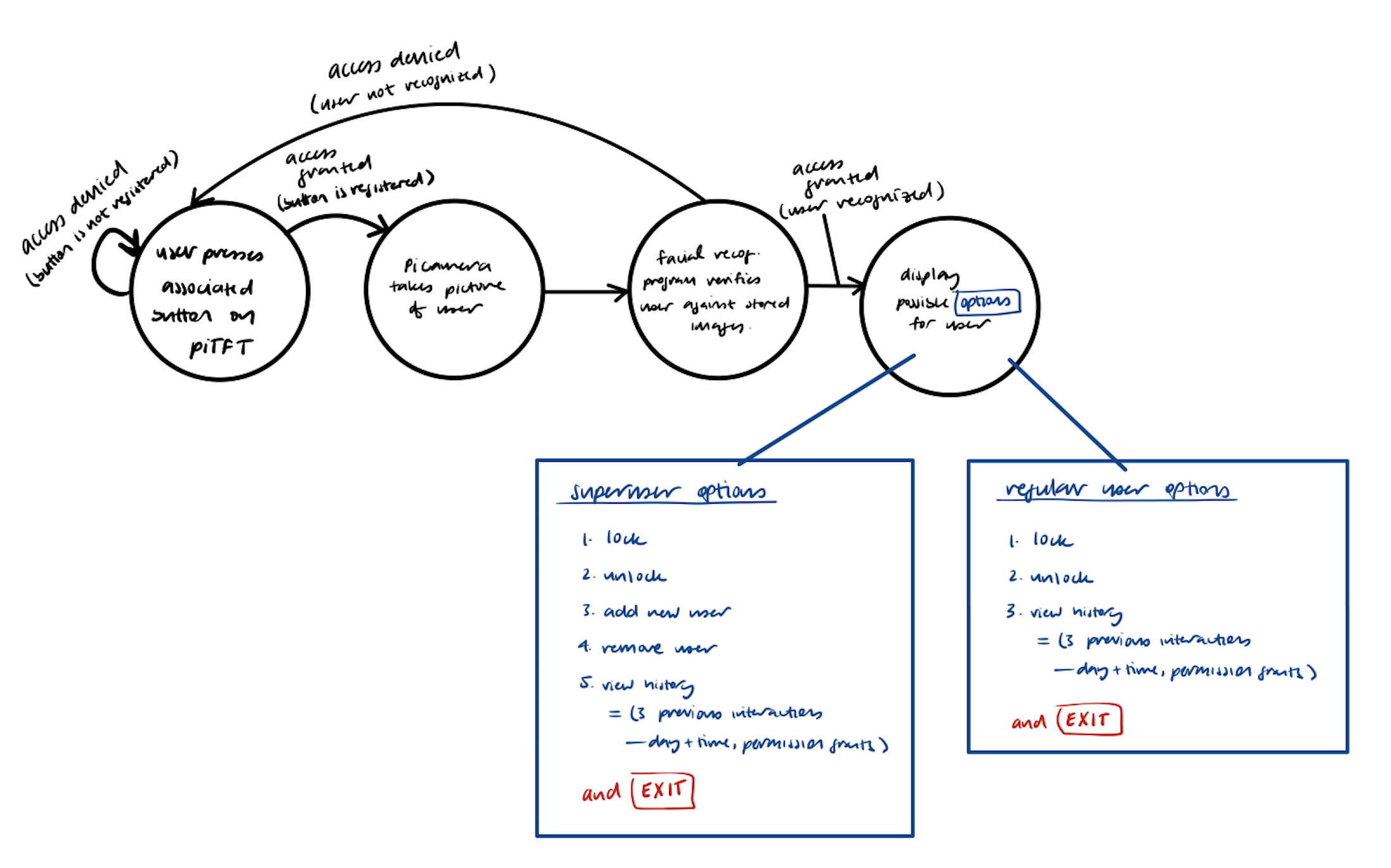
We wanted our final project to avoid using the HDMI monitor, keyboard, and mouse, so that it would more
closely
resemble a real embedded system. To do this, we created various displays for the piTFT screen. The
following FSM depicts our guiding vision for the piTFT display:
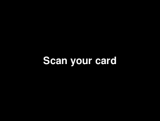
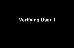
The initial display would request the user to "Scan your card" (or more likely, press their respective button), and then wait for system verification via the facial recognition module:
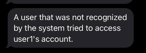
If the user was not verified (i.e. their image was not recognized by the system due to them not actually being the user or the environment/lighting quality was too poor for the piCamera to discern the user), then an error message would pop up on the screen and the user would need to try again. As an added security measure, we created an automation with IFTTT (If This Then That) to send a text message to Anusha's phone whenever a failed access occured. Whenever a user's image could not be identified, our code made an API call to IFTTT. The applet we created with IFTTT then trigerred a text message to be sent to Anusha's phone through ClickSend, a mass SMS sending platform. The "Acess Denied" screen and an example text message can be seen below.

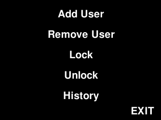
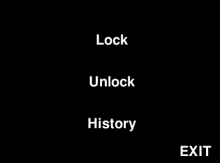
Once a user was verified, one of two menu options would display. These two menus differ with respect to the type of user that is accessing the system –– whether they are a regular user who can only lock, unlock, and view their access history or a superuser who has additional capabilities of adding and removing other users.
Upon selecting to lock the lock or unlock the lock, the linear actuator will retract or expand accordingly, and rest in the appropriate position.
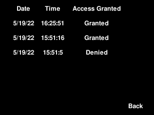
Users can also view their three most recent access attempts to the system, which stores the date and time of access as well as if the access was granted or not.
Superusers have the ability to add other users to the system. This is a two-step process -- first the button they want associated with the user must be pressed, then the user must then stand in front of the camera to allow for their picture to be taken for use by the facial recognition module. If the facial recognition module was able to verify the user in the images, the user will be added. Otherwise, if the user's face was not discernible in the pictures that were taken, the user will not be added, and must try again.


Superusers also have the ability to remove other users from the system. In order to do this, the supermust must simply press the button associated with the user they would like to remove.

Thus, once a user gets removed and their respective button is no longer associated with anyone, they can no longer enter the system, and instead see a "user does not exist" screen, as shown in the following image.

Each menu display also had an EXIT button so users could exit the menu screen once they were done with their required actions. This EXIT took users back to the initial "Scan your card" screen so that another user could then access the system.
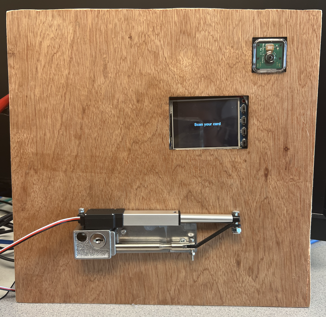
Week 5
This final week was devoted to working on the project write-up (website) and final demo. We made a demo setup using a piece of wood we laser cut to fit the RPi piTFT screen+buttons through as well as the piCamera. We also drilled our lock setup into the board. This aimed to create an environment similar to that of an actual door lock mechanism on a wall and door. The following is our final demo setup:
Results and Conclusion
We are satisfied with the end result of our project, though we were not able to accomplish one of our main
goals. Our
original design
integrated a more sophisticated two-factor authentication to grant users access to the system –– the first
method of
authentication would have involved a user-assigned RFID tag, which would be scanned by an RFID receiver. If
recognized by the
system, the system would then use the piCamera to scan the user’s face and use facial recognition to either
grant access if the
user is the correct individual associated with the tag, or deny access if the user if not the correct individ
ual associated with
the tag. At the beginning of working on this final project, the RFID receiver was the first task we worked on
connecting to the
RPi. It was originally successful, however, after approximately two weeks, our RFID receiver stopped reading our
RFID tags.
We were able to move on from this unfortunate hurdle by switching to using the piTFT buttons as the first system
“authentication”.
This allowed us to move forward with our project and focus on the more involved second measure of authentication
–– facial
recognition –– as well as the user-specific actions upon being granted access to the smart lock system.
We are happy with the accuracy of our facial recognition system for the size of the project. The
system is able to differentiate between users easily, and typically recognizes new photos of users as long as
the lighting conditions are not too poor. The system is also quite efficient for its size. It takes about thirty
seconds to add a new user and about a minute to remove one.
Using an incremental design process, as well as using GitHub to store our working files, we were able to
complete this project at a good pace and by the deadline.
Future Work
Given more time, we definitely would have liked to experiment more with the RFID receiver. An idea we did not
get to explore was
working with a voltage amplifier to drive the RFID with 5V from the RPi, as opposed to the general 3.3V.
Additionally, we wanted to integrate "promote user" and "demote user" functionality so that users could go from
regular users to superusers and vice versa.
Finally, if we had more time we would modify our system to accomodate more users. Currently all the user
training images, the encoding information, and the access history are all stored on the RaspberryPi. Since we
did not have more than three users, we had enough storage, but for a realistic system with more users than that,
we would need to integrate another data storage method, such as an online database.
Budget and List of Parts
| Item | Price | Source |
|---|---|---|
| Raspberry Pi 4B 2GB | $35 | Lab |
| PiTFT 2.8" Touchscreen | $34.95 | Lab |
| Pi Cobbler + Breakout Cable | $6.50 | Lab |
| Red and White RPi4 Case | $5 | Lab |
| SD Card 16GB | $8.95 | Lab |
| Jumpers | - | Lab |
| Linear Actuator (50mm stroke, 50:1 ratio, 6 volts) | $70.00 | Owned (Alisha) |
| Patio Door Lock | $23.65 | Owned (Alisha) |
| ClickSent Text Message Service | $20.00 | Purchased (Anusha) |
| Total | $204.05 | |
| Actual Expenditure | $20 | Items bought for this project |
The Team
Alisha Kochar
Electrical and Computer Engineering, MEng 2022
ak2255@cornell.edu

Anusha Nambiar
Electrical and Computer Engineering, 2022
aan29@cornell.edu
We worked on this project collaboratively. Initially, Anusha worked on the Facial Recognition module, whereas Alisha implemented the RFID detection module and linear actuator functionality. Once the RFID module stopped working on our RPi, we worked collaboratively to explore other outlines for our project and moved into collectively designing the piTFT display as well as user functionality for our Smart Lock. We used GitHub to maintain the code base and updated each other frequently on new thoughts and ideas. We completed the documentation and website together as well.